Pre-heating season checks
Before the heating season (or if the heat pump has been switched off for a long period) there are several preventative maintenance tasks that can be performed to help identify potential problems before the weather gets colder.
- Installers
- 6 min read
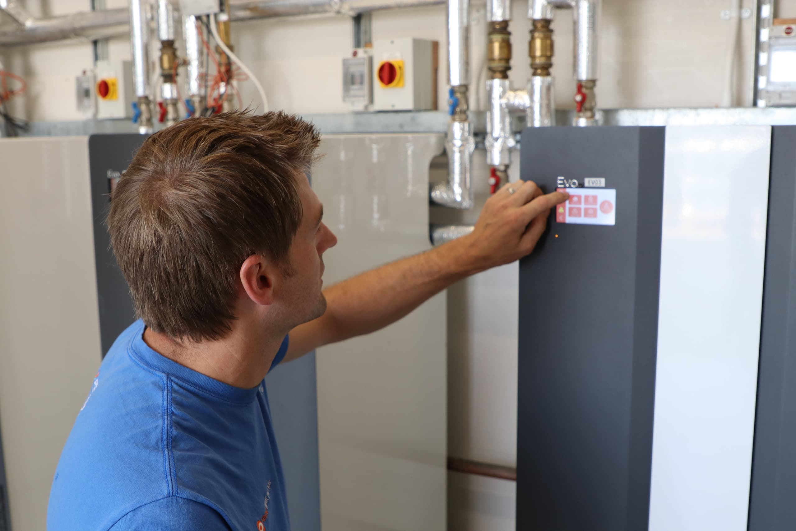
- Remove Front Cover. Use a 3mm Allan key to remove the 4 screws (2 each side). Depending on the space around the heat pump, you may also want to remove the lower side panel (again using a 3mm Allan key) or lift the top cover (by removing the 4 Allan screws and lifting). If you have to completely remove the top cover, then unplug the cable to the remote display.
- Turn off the heat pump internally. Turn the compressor(s) off using the 25/32 Amp MCB(s) and turn the controls off using the 4 Amp MCB(s).
- Check fluid pressure. Both the ground side and the heating side pressures should read higher than 1.8 Bar. You can top up the ground pressure side using the built-in filling valve which is on the right hand side towards the back or underneath the heat pump. The heating fluid pressure will be topped up by whatever system the original installer used. Typically there will be a filling loop somewhere near the expansion vessel.
- Bleed air. Two bleed ports are built into the heat pump – one for the ground side and one for the heating. The bleed ports are located at the highest point which means they are often easier to access if you remove or lift up the top cover (see above). Unscrew the cap (finger tight) and then depress the Schrader valve using a small screwdriver until the fluid runs air free. Be ready to catch the fluid in a container to prevent it flowing over the heat pump. Also bleed the heating side using any valves that may have been installed by the original plumber (e.g. radiator valves, underfloor heating valve or air vents at high points in the pipework). You may need to top the pressure up again (see above) once the system has been bled.
- Check pumps. Undo the large plug on the front of the heating-side water pump (using a container underneath to catch any fluid that may dribble out). Spin the pump using a smaller screwdriver to make sure it rotates freely. Turn the heating system on (using the heating system timer and/or thermostats) and turn on the 4 Amp MCB(s). The display should light up and the heating system pump should start running. Check the motor shaft is actually spinning. Replace the plug back into the front of the pump and repeat the process for the ground side pump. Note: the ground side pump switches on a few seconds after the 4 Amp MCB(s) have been turned on – you can often hear a small “clunk” as the contactor engages. You may need to bleed air and/or top up the system pressures again after checking the pump operation.
- Test anti-freeze. When the system was installed, the antifreeze concentration should have been checked but if that wasn’t done or if large amounts of mains water have been added into the system since installation the antifreeze may not have enough concentration. If you suspect this then you should check the concentration. Take a sample using the ground side Schrader valve and test with a refractometer to ensure the system is protected down to -10oC or lower. If you do not have a refractometer then we will be happy to test your anti-freeze sample and can provide sample tubes on request.
- Run compressor. Once you confirm that the system has enough pressure, is air free and the pumps run correctly, turn the 25/32 Amp compressor MCB(s) on to run the compressor(s).
- Check B readings. B02 is the temperature of the flow from the ground to the heat pump, B03 is the temperature of the return from the heat pump to the ground. There should be a difference of 5-7oC between B02 and B03 and the difference should not be higher than 10oC. Both temperatures should stabilise after around a few minutes of running. If B03 continues to drop it indicates that there is no or very little flow through the ground side. This will need investigating and correcting for the heat pump to operate correctly.
- Re-assemble unit. Check that the pump front plugs and the Schrader valve covers are replaced. Fit the top cover first (replacing the cable to the remote display if it was removed) and replace 3mm Allan screws. Then fit the side cover and finally the front cover.
Fault codes: What to do
Thanks to Kensa’s simple controls and technical support, should a fault occur with a heat pump, it is usually very quickly, easily and cheaply fixed. Fault codes for a Kensa heat pump are listed below, along with the steps you should follow to fix them:
- tP Is the most common fault code encountered, this is simply an indication of low water pressure on either the heating side or the ground side. The pressure on both circuits needs to be at least 1.8 Bar. (The gauges are not calibrated instruments and are quite difficult to read so assume 2 Bar). Trick: See step 3 in the above article.
- Hp This usually indicates a problem with the flow, or lack of it around the heating circuit. Check the heating circuit pump (Trick: See step 5 in the above article) – If this is ok, then the problem is likely to be the heating system.
- Lp This usually indicates a low or no flow problem on the ground side, sometimes goes hand in hand with A1. Check the ground heating pump (Trick: See step 5 in the above article) and B Readings (Trick: See step 8 in the above article). If this does not resolve the alarm, then contact Kensa.
- A1 At this time of year this normally indicates a problem with flow on the ground, side similar to Lp. Later on in the year it may indicate a problem with the setting of the A1 alarm, an antifreeze concentration issue, or the ground temperature. Trick: Check step 5 & step 8 in the above article, and contact Kensa if these do not resolve the alarm.
For more information:
Consult the relevant manual for your heat pump; all the manuals and much more technical information can be found at our online information library,  Pre-heating season checksResourcethe Knowledge Hub .
Alternatively, contact the Kensa technical department on 0345 222 4328.


